Posts

Showing posts from June, 2020

The Raspberry Pi Platform and Python Programming for the Raspberry Pi ( Week 4)

Build a circuit using your Raspberry Pi that causes an LED to blink when a push button is  NOT  pressed. However, the LED should stay on continuously when the push button  IS  pressed. Your video should show the LED blinking when the push button is not pressed, and it should show that the LED is continuously on while the button is pressed. Take a video of your circuit demonstrating the required actions and submit a hyperlink to your video's location on the Internet. Do  not  upload a video here. >>> https://drive.google.com/file/d/1hpyWED9n5G08zKCcJRRrTV1MhjHXhc5_/view Code for the Raspberry Pi Board for this project >>> import RPi . GPIO as GPIO import time GPIO . setmode ( GPIO . BCM ) ledPin = 18 buttonPin = 17 GPIO . setup ( ledPin , GPIO . OUT ) # LED pin set as output GPIO . setup ( buttonPin , GPIO . IN , pull_up_down = GPIO . PUD_UP ) # Button pin set as input w/ pull-up while True : try : if GPIO

The Raspberry Pi Platform and Python Programming for the Raspberry Pi (Week 3)

Image
Write a Python program that prompts the user to input 3 numbers, one at a time (see Instructions section for more details). Turn in your source code showing a full execution of your program and the result that it prints to the screen. >>> Upload a screenshot showing a full execution of your program and the result that it prints to the screen. In the execution that you take a screenshot of, you should enter the numbers in  non-sorted order  so that we can tell that sorting did occur. >>>

The Raspberry Pi Platform and Python Programming for the Raspberry Pi (Week 2)

Image
Boot the Raspberry Pi and install the “scrot” program to take screen shots. You can install it by typing “sudo apt-get install scrot” in a terminal window. Use the scrot program to take a screenshot of your Raspberry Pi. You will need to submit the screenshot as evidence that you completed the task, but you should submit the screenshot using your Raspberry Pi. I recommend using Epiphany as the browser since it is packaged with the Raspian/NOOBS installation. >>>

The Raspberry Pi Platform and Python Programming for the Raspberry Pi (Week 1)

Image
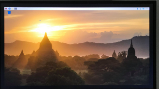
Setup your Raspberry Pi by using NOOBS to install Raspbian on the micro SD card. Boot your Raspberry Pi to the desktop and take a picture (with a regular camera/phone) of the desktop. >>>

The Arduino Platform and C Programming (Week 4)

Write a program that allows the user to control the LED connected to pin 13 of the Arduino. When the program is started, the LED should be off. The user should open the serial monitor to communicate with the Arduino. If the user sends the character '1' through the serial monitor then the LED should turn on. If the user sends the character '0' through the serial monitor then the LED should turn off. If you do not have an Arduino, you can use the web-based Arduino simulator at www.tinkercad.com. You will need to create an account for free. There are instructional videos on that website that will teach you how to use the simulator. >>> # define BAUD_RATE 9600 char incomingByte = ' ' ; void setup ( void ) { Serial. begin (BAUD_RATE); pinMode (LED_BUILTIN, OUTPUT); } void loop ( void ) { if (Serial. available () > 0 ){ incomingByte = Serial. read (); // Serial.println(incomingByte); if (incomingByte == ' 1 ' ){ d

The Arduino Platform and C Programming (Week 3)

Image
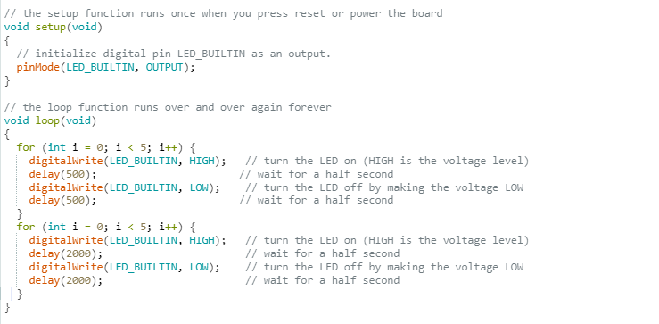
Write a program that causes the built-in LED connected to pin 13 on the Arduino to blink, alternating between fast blinks and slow blinks. The LED should blink 5 times quickly and then it should blink 5 more times slowly. When blinking quickly, the LED should have a 1 second period, so it should be high for 0.5 seconds and low for 0.5 seconds. When blinking slowly, the LED should have a 4 second period, so it should be high for 2 seconds and low for 2 seconds. The LED should continue to blink in this alternating fashion for as long as the Arduino receives power. Make sure your program compiles. Then, save a text version of your program and upload it here. Do not upload the executable file. >>>

The Arduino Platform and C Programming (Week 2)

Write a program in C that computes and prints out the first six digits in the Fibonacci sequence. Look up the definition of the Fibonacci sequence if you don't know it. The first two numbers in the sequence are 0 and 1, but your program should compute the next four digits. Make sure your program compiles using gcc. Then, save a text version of your program. Copy and paste the text of your program in the box here.  >>> #include<stdio.h> int main() {      int i, n=6, t1=0, t2=1, nextTerm;      printf("Fibonacci Series: ");      for ( i=1; i<=n; ++i)      {            printf("%d, ",t1)            nextTerm = t1+t2;            t1 = t2;            t2 = nextTerm;      }      return 0; }         

The Arduino Platform and C Programming (Week 1)

Image
1.         Install the Arduino IDE on your computer. Compile the "Blink" example, upload the example to the             Arduino board, and make sure that the LED blinks. Use the  www.tinkercad.com ​ simulator if you                 do not have the Arduino hardware.            Take and upload a screen shot that shows the "Done compiling" message and the byte number                 information in the message area. >>> 2.       Install the Arduino IDE on your computer, compile the "Blink" example (review Lecture 3.2 for a                  refresher). Then, upload the example to the Arduino, and make sure that the LED blinks. Use                    the www.tinkercad.comsimulator if you do not have the Arduino hardware.           Take and upload a screen shot that shows the message area after successfully uploading the                    sketch. >>> 

Intrduction to the Internet of Things and Embedded Systems (Week 4)

Image
Download and install Wireshark on a computer. Start a web browser on your computer and start packet capture with Wireshark. Use your browser to go to the website of CNN. Stop packet capture with Wireshark. Using Wireshark, find the HTTP packet which was initially sent by your browser to the New York Times web server to request the page. Select that request message and submit a screen dump (print screen) of Wireshark displaying the request. Save that screen dump and upload it here.

Introduction to the Internet of Things and Embedded Systems (Week 3)

1.       Research two microcontrollers and provide information about them from their datasheets. There                are several microcontroller manufacturers that you can investigate including Atmel, Microchip,                  Freescale, TI, etc. For each microcontroller, report the following information. (Be sure to include a              link to an online reference where you found this information.)   Clock frequency Bitwidth of the datapath Size of Flash memory Number of pins Does the microcontroller contain an Analog-to-Digital Converter? If so, how many bits of precision does it have? >>>     ATmega32 - RenesasRX   Clock Frequency : 1 MIPS - 240 MHz   Bitwidth of the datapath : 8 bit - 32 bit   Size of Flash memory : 32 KB - 512 KB   Number of pins : 44 - 64   Analog to Digital converter : 10 bit ADC - 12 bit ADC                    Link for ATmega32 :   https://www.microchip.com/wwwproducts/en/ATmega32          Link for  RenesasRX  :   https://

Introduction to the Internet of Things and Embedded Systems (Week 2)

1.        Identify two embedded systems that are sold on the market today and analyze their interfaces. >>>      DIGITAL CAMERA       A digital camera is very good example of Embedded system.       Cameras that we use today are smart and have a lot of features that were not present in early        cameras all because of embedded system used in them.       A digital camera has basically three functions, to capture image which we call data, to store            image data, and to represent this data.       Today images are stored and processed in form of digital data in bits.           HOME SECURITY SYSTEMS       Home security systems has another good example of Embedded systems.       These systems have several features just as checking for fire or gas leakages, and detecting if        someone suspicious tries to enter the house.       If family members are not present in home then still they can monitor the activities going on in        their house. 2.   

Introduction to the Internet of Things and Embedded Systems (Week 1)

1.       Identify and analyze a device that is an IoT device now, but in the past was a non-IoT device .                   Describe and list the features of the device. Compare the functions of the device in the past to the             functions of the device now. >>>    Old traditional watch :                     Needs Battery           Smart IoT watch :                     Contains different sensors                     Chargeable                     Calculates many things in our body such as Blood Pressure, Heart rates etc. 2.        Compare the functions of the device in the past to the functions of the device now. >>>      Old traditional watch :                     Shows only time           Smart IoT watch :                     Shows time                     Calculates Heart rates, Blood Pressure etc.                     Connects to the smart phones 3.        For your chosen IoT device, list any improvements or any dimin